In order to start writing my program, I first have to recognizes my ouput and input for my ARDUINO UNO to be "talking". So far, I have to project 3 outputs from my ARDUINO. Before it can be projected, I must use the XBEEs to convey information from my other ARDUINO board, that is from the Infusion Pump. Actually the Infusion Pump is my partner's part, but I also have to know which pin configurations that she is using at her ARDUINO so I can "call" or receive the data to display it at my outputs.
For this moment, I have only 3 output that is first, the LCD. I am using 16x2 Liquid Crystal Display and the LCD will be connected (hopefully I can get it done by Monday) to my ARDUINO UNO.
 |
| 16X2 LCD According to the data sheet, this LCD have a contrast that can be adjusted using a 10KOhm potentiometer. The pins that I will be using to connected to the ARDUINO UNO are: |
16-GND, 15-5V, 3-middle potentiometer (adjusting contrast) 5-GND (RW:not used because this is if we want to send it to ARDUINO), 4-7(RS), 6-8(EN), 14-12(DB7), 13-11(DB6), 12-10(DB5), 11-9(DB4).
So initially, I will use up Arduino pin 7,8,12,11,10 and 9. It is useful to record or jot down properly because I will use this up to write my program. The LCD should display such things as "OCCLUSIONS, FINISHED, BUBBLE, or ERROR" to alert the person that is monitoring the system.
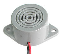
The second output is a buzzer to alarm the person in charge at the monitoring system. I will be using BUZZER to demonstrate the alarm system by beeping sounds.
 |
| Buzzer |
The buzzer is the simplest connection since the GND will be connected to GND ARDUINO (at the DIGITAL part) , and the other wire will be used to connect at pin 6 at the DIGITAL part of ARDUINO. The data will be sent from XBEE to the BUZZER through different melody to indicates the condition of the infusion pump.
The third output will be my 7 segment which will display the number of bed patient since I am making this monitoring system for many patient beds. Hm...I am not sure how am I going to connect them.. Actually I am just going to plug 8 LEDS and which bed have the problem will light the LED. But now, with too many pins by the LED makes my connections full. Not including the XBEE I want to use!!!So how am I going to connect these 8 outputs??????????
But I am sure the 7 segment would be just fit. Let's search for the datasheet.
OOOOKAY... The 7 segment have 8 LEDs so I have to connect 8 LED to ARDUINO UNO. WHAT????? I only have 6 pins left untouched!!Hm... Not to worry..There are such thing called demultiplxers that will be used to convert the BCD to ordinary Decimal at the 7 segment. So I will use another 4 connections from the UNO to be connected at the latch at the decoder (4511 IC). *Note to self: Check weather the 7 segment are common anode/cathode.
Example of a common cathode connected to a decoder.
So basically I am off to program the outputs except for my 7 Segment because I haven't decide which connection yet. I hope tomorrow I can finish programming these 2. :)


No comments:
Post a Comment