WELLCOME -----FYP S2 2011 PROJECT BLOG-----SUPERVISED BY: SIR KAMALUL FAIZIN B. MOHD SUHUT

Sunday, February 27, 2011

INNA LILLAHI WA INNA ILAIHI RAAJI'UN... (TANBIHUL GHAFILIN)


Alhamdulillah, praise to ALLAH for giving us time and health in doing this final year project. Today, I am not talking about my project, just a bit of thoughts that I would like to share to you all my dear friends, about my experience in the making of this project.  In the excitement of exploring Alduino and Xbee, I would like to advice me, my partner and my viewers about the importance of staying grounded, stable, alert and the awareness of we also have another destiny, the Akhirah. 

 As we can see today this world is living in massive madness, madness that is created and continuously being influenced day by day, through the excitement of entertainment. We have to realized that the entertainment that is attacking our brain and thoughts does not only comes from the singers and televisions, it also comes in a variety of fields, not to mention that it was very very fine and never can be detected with our naked eyes.  


 For example, this electronics field is really exciting and fun to explore, and it would be really great if we use the technology to raise our Ummah. Yes, we are all in the process of learning and exploring, but please remember and please note to yourself, that we are doing this to learn the knowledge of the technology world, all because of ALLAH. I am writing about this today because I am once lost  in my own electronics world. Weeks before this post is published, I am ambitious about my project, I want it to be really good to impressed lecturers, friends and my future employer. I want it to be good so bad that I am scared that I will fail it and it will effect my job applications after I am done studying at UniKL BMI. Not that I am saying that it is bad to be ambitious, I am warning you about the excitement that will leads you to forget about your main purpose of living in this world, that is to be the Khalifah to other creatures. 


Then I look back and started to realize that our religion teaches us to be modest about anything, in everything. So from now on, that is what I am going to do. I changed my motives to learn about this field all because of ALLAH, not to impressed other people. ALLAH is the one who have to be satisfied, not anybody, since He is the King of all kings. I feel so much more motivated, plus I have no fear anymore that this project will cause me trouble or failure, since I am now working very hard on it plus I am practicing tawakkal to ALLAH! I will leave everything to ALLAH once I did all my efforts.

We are literally running out of time, the clock is ticking and we are all headed to that one place, that is Akhirah. So wake up,  pray for guidance and ALLAH's forgiveness everyday, work like you live forever and pray, worship Allah like there is no tomorrow.  May ALLAH blesses us and have mercy on our soul...


 From Ibn. Umar Radiallahu Anhu
Allah's Apostle said, "Amongst the trees, there is a tree, the leaves of which do not fall and is like a Muslim. Tell me the name of that tree." Everybody started thinking about the trees of the desert areas. And I thought of the date-palm tree but felt shy to answer the others then asked, "What is that tree, O Allah's Apostle ?" He replied, "It is the date-palm tree."


Friday, February 25, 2011

AIYA!!!NOT ENOUGH CURRENT??

Well firstly I would like to say: Currents are crucial!!!!! Don't take it easy or your project will not function! Em.. As you all know I've been setting up my LCD and 7 segment display... Apparently.. Guess what... The 7 segments are working all weird.. By weird, I mean that some of the lights are dimmer than the other, and only one segment, that is the "g" section got so bright, seriously u have to wear glasses! After a long hardwork trying to figure out what could have been wrong at my circuit, I went to internet and.. YIKES!!!


                        What went wrong was: 
1) If u are using the 74HC595, u actually need an IC that is called IC driver to make sure u deliver enough current for the 7 segment display. The ones that are seldom shown to u by blogs or what so ever don't mention this because they use LEDs to displays the lights. (Credit to Mr. Azmi for mentioning this earlier but I took his advice for granted :( )

2) The 7 segments acting up all wired when it is combined with LCD circuit because the LCD also takes up a lot of currents and furthermore, it uses the same 5V from the UNO.

So there u go guys... Actually I have a test at 3 pm, so I'll upload pictures of my ruined 7 segment circuit later this evening. So keep up the good work guys.. Surviving FYP!!! :)

Friday, February 18, 2011

OUR BUDGET-SO WE DON'T FORGET

Ok, this post will always be update by each weeks because we dont want to lose and forgot to includes our budgets for our purchasing. This post is also important since the budgeting is in the FYP REPORT.


Arduino UNO                - RM 109.00 X 2 = RM 218
XBEE Shield                 - RM 165.00 X 2 = RM 330
JHD LCD Display        - RM  25.00 X 2  = RM  50
Jumper Wire                 - RM  18.00  X 1 = RM  18
IC LM 293                       - RM     8.00 X1  = RM    8
7 Segment  (CC)           - RM    3.00  X 1 = RM    3
PCB Buzzer                  - RM     2.00 X 1 = RM    2
AA Battery Holder        - RM         1 X 1  = RM    1
IC 74HC595                    - RM     1.70 X 1 = RM    1.70


Current Total                                           = RM 631.70


There are such things that we don't have to buy, thanks to Sir Kamalul Faizin, who has lended us his stepper motor and another IC LM293. Alhamdulillah, we also didn't have to buy power supply to support current to drive the stepper motor also because of his generosity. :)      


That is all for now, we will update another post next week about our 7 segment and motor assembly. Next week is also our phase test week so pray for us guys~~ :)    

EXCITING HANDS-ON TIME... :)

           Okay..Sorry to kept anyone who is reading this blog to wait for our new post... Well as you all know that the unexpected happened, so we figured it would be better for us to just continue with our current progress.. As soon as we got the UNO, we couldn't keep our hands off it!! We kept testing the programs that have in the examples from the Tutorials forum and it goes without saying, IT WORKSSS~~~ :D As we both are excited, first we tested to both our UNO using the blinking LED program to make sure it's transferring the right data. (Of course u wont see it's blinking in this picture)


                                                                   Blinking LED worked!


             Then, we soldered the LCD (16X2) to the right connection, to get it ready to run at the UNO. First, we set the contrast. By setting the contrast, there are some soldering needed. After that, we connected the UNO to a USB cable, and don't worry,  the cable is the same as your printer cable. This step is crucial, you cannot GO FURTHER until you get this kind of output. *The connections are based on the previous post about configuring pins.


          After that, we connects the data lines from the LCD to the monitoring UNO. Also, the pins are from the previous post. So when the jumpers are connected, we run our testing programs from the ARDUINO Software and VOILA!!!!


Then all other test were just playing around such as:


And credits to our new freind, Azmi :)


Friday, February 11, 2011

THE UNEXPECTED

Just got my UNO boards. Yippie!!! The sad thing is I got them Wednesday which was later in the afternoon. The XBEE SHIELD has arrived two days earlier, but the problem is the other XBEE is out of stock. So I only have one XBEE to program and I didnt even know how to.


Then.. I did not get any of my plans work this week. This is because I hadn't get the chance to buy the shift register. T_T

Saturday, February 5, 2011

74HC595-8 BIT SHIFT REGISTER

Table: Pin outs from PHILIPS DATASHEET
This post continues my search of finding the lowest o/p number to be connected to my UNO. Alhamdulillah, I have found a solution that only requires 3 pins connected to my UNO, and it is:
74HC595 Shift Register (Figure: Courtsey of Open Source Notes)

Actually the schematic above is from Arduino notebook and it is connected to 8 LEDs. But for my project, I will use the 7 segment to display the number of patient's bed. The 7-segment LED pins are:
*Compare these to the real datasheet pins because there is a website telling that a datasheet was wrong. Maybe I'll make 2X7 Segment because it is ridiculous not to be able to display 2 digits in a monitoring system. However, it will double the connection to 6 o/p pins. So it's a challenge for the Number of Bed display part. I'll check back on it later.  
The conclusion is, the 74HC595 have 3 inputs to be connected to my UNO, that are:
  1. DS (pin 14) to Ardunio DigitalPin 13
  2. SH_CP (pin 11) to to Ardunio DigitalPin 4
  3. ST_CP (pin 12) to Ardunio DigitalPin 2
The remaining pins that I haven't connect are:
AREF, 0-RX, 1-TX, 3, AND 5. 
Alright!!! Time to sketch the outputs! I must jot these all down in the log book because I will refer and use this a 1000 times :)

PROGRAMMING-PIN CONFIGURATIONS.

In order to start writing my program, I first have to recognizes my ouput and input for my ARDUINO UNO to be "talking". So far, I have to project 3 outputs from my ARDUINO. Before it can be projected, I must use the XBEEs to convey information from my other ARDUINO board, that is from the Infusion Pump. Actually the Infusion Pump is my partner's part, but I also have to know which pin configurations that she is using at her ARDUINO so I can "call" or receive the data to display it at my outputs.

For this moment, I have only 3 output that is first, the LCD. I am using 16x2 Liquid Crystal Display and the LCD will be connected (hopefully I can get it done by Monday) to my ARDUINO UNO.

16X2 LCD

 According to the data sheet, this LCD have a contrast that can be adjusted using a 10KOhm potentiometer. The pins that I will be using to connected to the ARDUINO UNO are: 
16-GND, 15-5V, 3-middle potentiometer (adjusting contrast) 5-GND (RW:not used because this is if we want to send it to ARDUINO), 4-7(RS), 6-8(EN), 14-12(DB7), 13-11(DB6), 12-10(DB5), 11-9(DB4).

So initially, I will use up Arduino pin 7,8,12,11,10 and 9. It is useful to record or jot down properly because I will use this up to write my program. The LCD should display such things as "OCCLUSIONS, FINISHED, BUBBLE, or ERROR" to alert the person that is monitoring the system. 

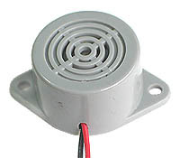
The second output is a buzzer to alarm the person in charge at the monitoring system. I will be using BUZZER to demonstrate the alarm system by beeping sounds. 
Buzzer
The buzzer is the simplest connection since the GND will be connected to GND ARDUINO (at the DIGITAL part) , and the other wire will be used to connect at pin 6  at the DIGITAL part of ARDUINO. The data will be sent from XBEE to the BUZZER through different melody to indicates the condition of the infusion pump. 

The third output will be my 7 segment which will display the number of bed patient since I am making this monitoring system for many patient beds. Hm...I am not sure how am I going to connect them.. Actually I am just going to plug 8 LEDS and which bed have the problem will light the LED. But now, with too many pins by the LED makes my connections full. Not including the XBEE I want to use!!!So how am I going to connect these 8 outputs??????????


But I am sure the 7 segment would be just fit. Let's search for the datasheet.

OOOOKAY... The 7 segment have 8 LEDs so I have to connect 8 LED to ARDUINO UNO. WHAT????? I only have 6 pins left untouched!!Hm... Not to worry..There are such thing called demultiplxers that will be used to convert the BCD to ordinary Decimal at the 7 segment. So I will use another 4 connections from the UNO to be connected at the latch at the decoder (4511 IC). *Note to self: Check weather the 7 segment are common anode/cathode.

Example of a common cathode connected to a decoder. 

So basically I am off to program the outputs except for my 7 Segment because I haven't decide which connection yet. I hope tomorrow I can finish programming these 2. :)


Friday, February 4, 2011

LESSON THROUGH YOUTUBE

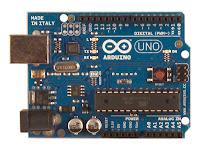
      Today, I bought 2 ARDUINO UNO boards to be used in my project through a website called myduino.com.
Arduino Uno (myduino.com)

        I was all excited until I was informed by the seller that the UNO would not be sent to me until next Monday because their company is close during the Chinese New Year Holiday. Ugh... Bummer.
But that's okay, I still don't have my XBEE shield with me anyhow so I guess it would be pointless if I had the Uno now.So now I don't have anything to do. Hm...
XBEE Shield (Maxstream)

           Wait, that seems lazy. Just when I'm about to hit the "The Sim's 2: Freetime" game, I notice that it would be nice if I learn to create the Xbee and ARDUINO UNO program! Plus, I have the program installed in mylaptop but I don't even know how to use or launch it.

         Then it just hit me that I have to start A.S.A.P or else this monitoring system would not finished!!!As I explore the programs, learn the language, I also notice that the XBEE SHIELD can be stick on the ARDUINO XBEE. But how am I going to upload a program if those pins are connected together??? I was puzzled by the fact that the RX / TX of the XBEE will surely stack on the UNO and it would be errors. during the uploading.

         So I went down to Google, play around in the internet, watch tutorials on Youtube and voila!!
There are actually solutions. Thanks to the power of internet (praise to ALLAH), I am now aware that:

1)If u want to upload any program to the ATMEL chip, just simply unstack the XBEE shield off the UNO board.
2) If u want to upload program to the XBEE Shield, take out the ATMEL chip from the UNO board, and stack back XBEE shield to UNO. (this is because the XBEE shield I use didnt have USB connector, only UNO has it). 

        So..end of today's work..tomorrow I hope I can create a program and on Monday I can test them  down to my UNO and XBEE shield. :)

Thursday, February 3, 2011

ACTIVATING BLOG

First time using blogspot.com. 


This is the first time that I used this blog as a diary. It is created  to write everything about my research, findings and pictures about my final year project at UniKL BMI.


It is also created as an evidence showing my enthusiasm for Electronics products and knowledge about new technology that changes my point of view to programming and hardware development, ARDUINO and XBEE MODULE. .
So far so good, thanks a lot to a father of mine who was helping me through the process of exploring blogs. 


p/s: Yes, I am a very lame teenager who didn't care of these things before but now I am all psych!!! :)